NO PHYSICAL CHASSIS
Packaging and branch lengths had to be established entirely from the evolving SOLIDWORKS Master assembly.
visitor@portfolio:~/projects/or27$ cat README.md
OWL’s Racing first fully CAD-designed vehicle harness—from electrical schematic to 3D routing and physical manufacture.
/ 01 — THE CONSTRAINTS
OR27’s electrical system needed to move forward before its physical chassis was available to alot the team time for testing a tuning the new powerplant for OR27. With no vehicle to measure, limited funding, and one person responsible for the harness, the conventional build-and-adjust process was not an option.
The solution was to depart from convention and make the digital model the source of truth and develop the electrical system concurrently with the rest of the car in SOLIDWORKS.
Packaging and branch lengths had to be established entirely from the evolving SOLIDWORKS Master assembly.
Electrical architecture, documentation, routing, and manufacturing were completed by one tired engineering student.
In order to meet the start or Spring Semester powertrain start date target the Vehicle Harness manufacturing would have to happen in two weeks over Winter Break
Due to the teams limited budget and ambitions overall vehicle goals, simplicity and low-cost manufacturing guided decisions without removing critical vehicle functionality.
/ 02 — DIGITAL-FIRST WORKFLOW
The complete electrical architecture was documented in SolidWorks Electrical. Those connections were then routed through the OR27 vehicle assembly in SolidWorks 3D, allowing branch paths, component interfaces, and packaging to be resolved before manufacturing began.
This was the first time OWL’s Racing developed a vehicle harness through a complete CAD workflow. It replaced physical guesswork with a documented process future teams can repeat and refine.
/ 03 — MANUFACTURE
The finalized digital routing became full-scale formboard drawings, generously printed by Dixie Prints. I taped them to the largest sheets of plywood I could fit inside my Corolla—32 × 75 inches—and began building the harness directly over the drawings.
I entered this phase with very little formboard experience, so the manufacturing method evolved quickly through failure. The first board used nails as routing posts. Under wire tension, those nails began to pull out of the plywood—lesson learned, and apologies to Professor Abtahi.
On the next board, I replaced the nails with screws that stayed firmly seated. Rubber bands stretched between pairs of screws added simple, inexpensive retention, preventing wires from lifting out of their routes while branches were measured, bundled, and terminated.
The harness was completed on schedule with full Bosch MS4 functionality and support for the vehicle’s complete sensor suite. More importantly, the two-week build turned an improvised first attempt into a repeatable manufacturing method the team can use again.
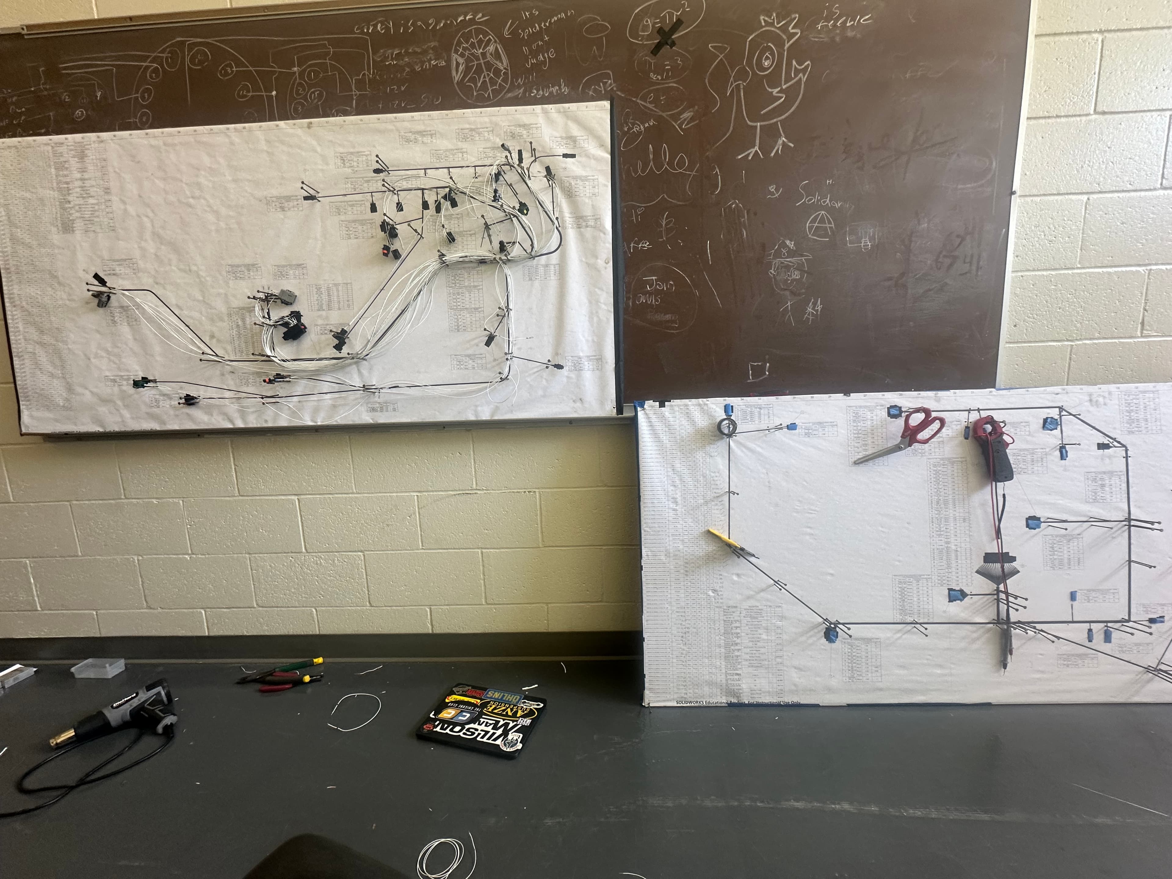
CAD → FORMBOARD ITERATION → CUT / CRIMP / ASSEMBLE → VALIDATE
/ 04 — SYSTEM + LEGACY
01Readable harness documentation
02Repeatable harness design workflows
03Reusable SOLIDWORKS connector and wire libraries
04Proven harness manufacturing method & tools
05Full Bosch MS4 functionality